Testing:
In which your humble author learns about CPU temperature measurement. It seems that the two most common ways of measuring CPU temperature are with a thermistor in the CPU socket and with a diode on the actual die. My motherboard is an ASUS A7V600-X which apparently has both. Needless to say the on chip diode is the more accurate sensor but the Windows based tools I used during construction did not indicate which sensor was in use.
When I started the project I guessed that there would be more tools readily available for Windows then for Linux for testing the CPU so I installed a copy of Windows 2000 on a disk for testing. I used Motherboard Monitor and SuperPI to monitor and stress the CPU.
Later I discovered that Linux actually had some better tools, namely lm_sensors and burncpu. I use Scientific Linux 4.2 so lm_sensors was already installed. Running sensors-detect and restarting lm_sensors with service lm_sensors restart got me up and running. the command watch sensors gave me a temperature reading that was updated every 2 seconds.
However, the MB and CPU label were switched and the temp didn't look quite right. I edited my /etc/sensors.conf and updated the it87 section to read:
# TemperatureThis gave me more reasonable readings. When testing with SuperPI on the Win2K disk or encoding with Lame on Linux I was able to get the CPU utilization to 100% but the temp only went up a few degrees. Running the Athlon optimized version of cpuburn caused the temp to climb much higher and much faster. The moral is an indicated 100% CPU does not always mean the CPU is maxed out as far as heat production is concerned.
#
# Important - if your temperature readings are completely whacky
# you probably need to change the sensor type.
# Adjust and uncomment the appropriate lines below.
# The old method (modprobe it87 temp_type=0xXX) is no longer supported.
#
# 2 = thermistor; 3 = thermal diode; 0 = unused
set sensor1 3
# set sensor2 3
# set sensor3 3
# If a given sensor isn't used, you will probably want to ignore it
# (see ignore statement right below).
label temp1 "CPU Temp"
set temp1_over 60
set temp1_low 15
compute temp1 (@+128)/3, (3*@-128)
label temp2 "M/B Temp"
set temp2_over 45
set temp2_low 15
ignore temp3
label temp3 "Temp3"
set temp3_over 45
set temp3_low 15
# The A7V8X-X has temperatures inverted, and needs a conversion for
# CPU temp. Thanks to Preben Randhol for the formula.
# label temp1 "CPU Temp"
# label temp2 "M/B Temp"
# compute temp1 (-15.096+1.4893*@), (@+15.096)/1.4893
# The A7V600 also has temperatures inverted, and needs a different
# conversion for CPU temp. Thanks to Dariusz Jaszkowski for the formula.
# label temp1 "CPU Temp"
# label temp2 "M/B Temp"
# compute temp1 (@+128)/3, (3*@-128)
# Fans
set fan1_min 0
set fan2_min 3000
ignore fan3
ignore fan2
ignore fan1
set fan3_min 3000
As I write this my temps are:
CPU Temp: +48°C (low = +15°C, high
= +60°C) sensor = diode
M/B Temp: +36°C (low = +15°C, high = +45°C) sensor = thermistor
M/B Temp: +36°C (low = +15°C, high = +45°C) sensor = thermistor
Which a little higher then I'd like but nearly identical to what it would be with the original heat sink installed.
| The first test was to just look at the temperature in the BIOS hardware monitor screen. | 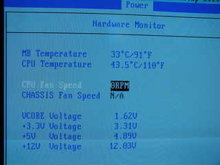 |
|
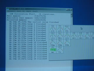
| Next I booted with Win2K and ran Motherboard Monitor. The temp was about 38
degrees C at idle and went up to 43 degrees when running SuperPI for a half hour. This was very encouraging but, as it turned out, not really a true test. |
 |
|
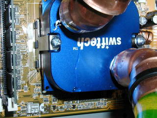
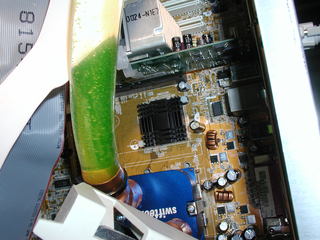
| I used Teflon tape to seal the water block fitting and the they leaked! Both
of them! |
 |
|
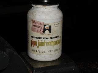
| I replaced the Teflon tape with good old pipe dope, bye bye leaks! |
 |
|
| The typical motherboard lives in a windy box, as such chips like this one are
cooled by the breeze from several sources. |
 |
|
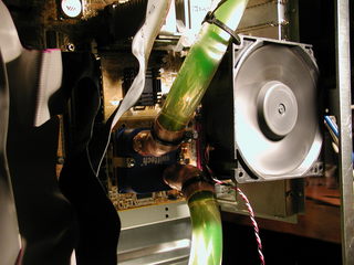
| This is the "Northbridge" and it got really hot too. |
 |
|
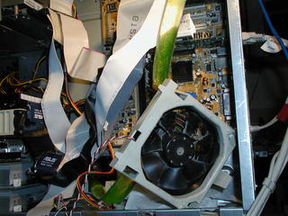
| I stuck one of the PowerEdge fans on these two chips to keep them cool during my
testing. |
 |
|
| Later I thought, "Hmm, I wonder what that fan would be like running on 5 volts?"
It worked very well indeed on only 5 volts. If you put your ear up to it
you could hear a small amount of motor cogging noise but no air noise at all. Rather then making water blocks for these two chips I decided to just install the "half" a fan to gently blow on the hot bits. |
 |
| <-- Previous | Next --> |
